3D Mapping with LiDAR
The current state of SLAM and some major problems with it

The Algorithm
The SLAM (Simultaneous Localization and Mapping) algorithm, when combined with LiDAR technology, endeavors to merge multiple LiDAR frames into a comprehensive 3D map. This process is analogous to stitching together multiple photographs to create a panoramic image, but with a significant twist: everything is in 3 dimensions, making it a far more intricate and complex task.
Here's the current frame of lidar
Here's the frame after it is transformed and added to the global map
The algorithm's primary objective is to compute R and t, namely, the rotation and translation that, when applied to the current LiDAR frame, aligns it correctly with the global map.
In LiDAR-based SLAM, it's rare to rely solely on LiDAR data. Instead, multiple sensors are typically fused together to generate the final map.
Commonly, you'll find a combination of LiDAR, IMU, and RGB cameras working in tandem for SLAM applications.
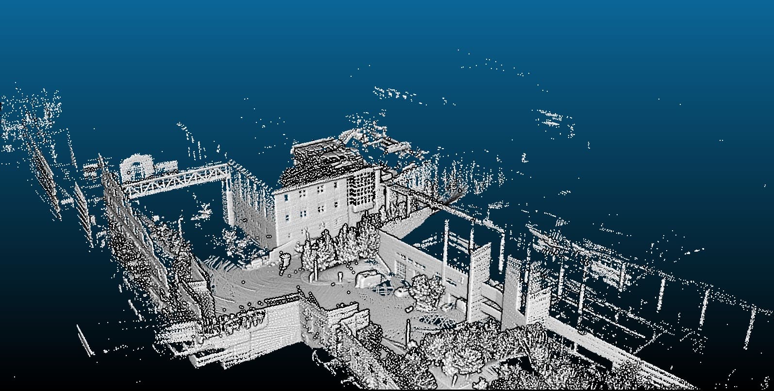
This blog post will focus specifically on 3D mapping for producing highly accurate point clouds, which are essential for as-built 3D services.
LOAM
This is Lidar Odometry and Mapping, a relatively straightforward process that involves taking LiDAR frames and attempting to stitch them together using a technique such as ICP (Iterative Closest Point).
However, relying solely on LiDAR data for odometry poses a significant challenge. The LiDAR itself is prone to noise, with typical errors ranging from ±1cm to ±2cm. To put this into perspective, a single LiDAR frame can contain 10-20 such error-prone measurements per second. This translates to a 2cm thick cloud of uncertainty for just one second of data. As you try to stitch these frames together over time, the errors will accumulate, leading to gradual drift.
Here's a LOAM implementation, quite old.
https://github.com/laboshinl/loam_velodyne
The LOAM algorithm is implemented in ROS and utilizes the Velodyne LiDAR, a legacy sensor that has since been acquired by Ouster.
One of the reasons LOAM struggles when the LiDAR is moved around is due to undistortion. You may have noticed that when taking a photo with your phone camera in low-light conditions, it prompts you to stay still; otherwise, the image appears blurry. Similarly, when a LiDAR sensor moves rapidly, the resulting point cloud becomes distorted and hazy. To correct this, additional sensor data is required to undistort the point cloud. While the effect may seem minor, it can accumulate over time and result in a noisy point cloud.
The most recent LiDAR odometry algorithm I came across is KISS-ICP, which can be found on GitHub: https://github.com/PRBonn/kiss-icp
SLAM like KISS-ICP take care of the blur issue by trying to deskewing the input point cloud based using kalman filter and trying to predict the pose, but having an IMU in this case would definitely help.
LIO
Lidar Inertial Odometry (LIO) takes the concept of LiDAR odometry a step further by incorporating an Inertial Measuring Unit (IMU). The IMU provides accelerometer and gyroscope values that complement the LiDAR frames, effectively merging two odometry sources. While it's possible to create an odometry solely from IMU data, it would inevitably drift over time. By combining both measurements, LIO achieves a robust odometry that's well-suited for scan-to-BIM applications.
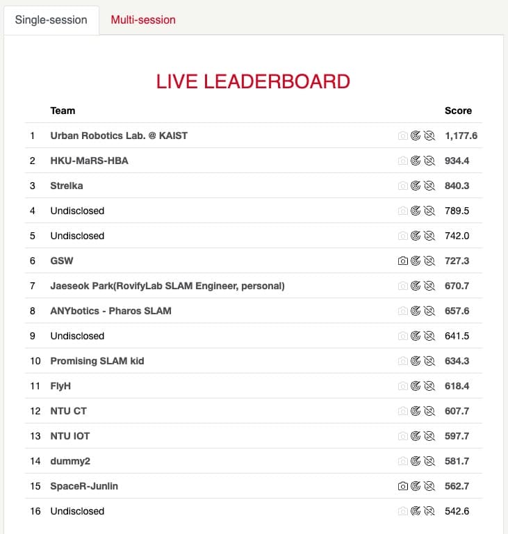
A glance at the Hilti SLAM 2023 leaderboard reveals that the top 5 algorithms are all LIO-based, with Ada-LIO from KAIST claiming the top spot.
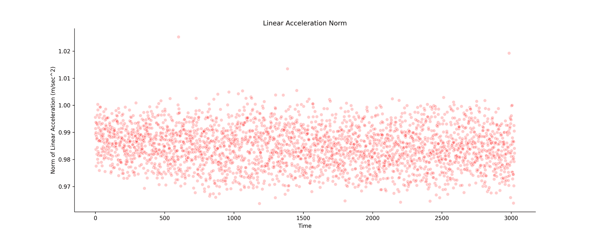
The problem with IMU is that it generates noise over time, and is related to the temperature, so if you are in a hot environment, more noise buddy.
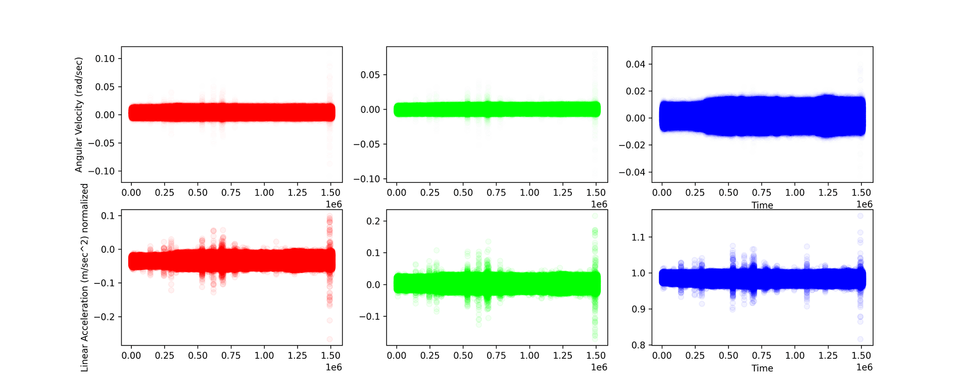
The IMU was kept stationary, on the x axis we have time in epoch, and y axis we have accelerometer values and gyration values. it's clearly visible that over time the noise increases, ofcourse you will need to put a kalman filter, but that will only help to some extent.
One popular open source LIO Algorithm is FASTLIO2 https://github.com/hku-mars/FAST_LIO. It was meant for real time slam, so if your lidar is 10Hz you get SLAM at 10Hz.
VIO
Visual Inertial Odometry. Now this is interesting, just the RGB camera is used to compute visual features, and the features itself are tracked using with Lucas Kanade or Optical Flow.
ORB SLAM 3 is the most widely known Odometry with Camera https://github.com/UZ-SLAMLab/ORB_SLAM3
It need not be necessarily a RGB Camera, it could also be something like an IR or a NIR Camera as well. Most of the time the input frame is converted to grayscale as feature detectors expect a mono image. So any kind of camera that gives really good quality features would work.
LIO + VIO
The final odometry is obtained by fusing both Lidar Inertial Odometry (LIO) and Visual Inertial Odometry (VIO) together.
However, a crucial challenge lies in the requirement for hard event synchronization between the camera and LiDAR, ensuring that the image data is precisely aligned with the LiDAR scans. Additionally, the images themselves must possess a sufficient number of features that can be tracked reliably. If these conditions are not met, the entire system can become unstable and unreliable.
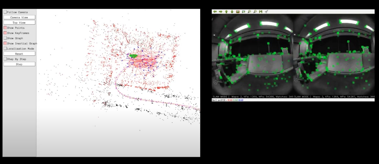
The most popular SLAM for fusing VIO and LIO is R3LIVE: https://github.com/hku-mars/r3live
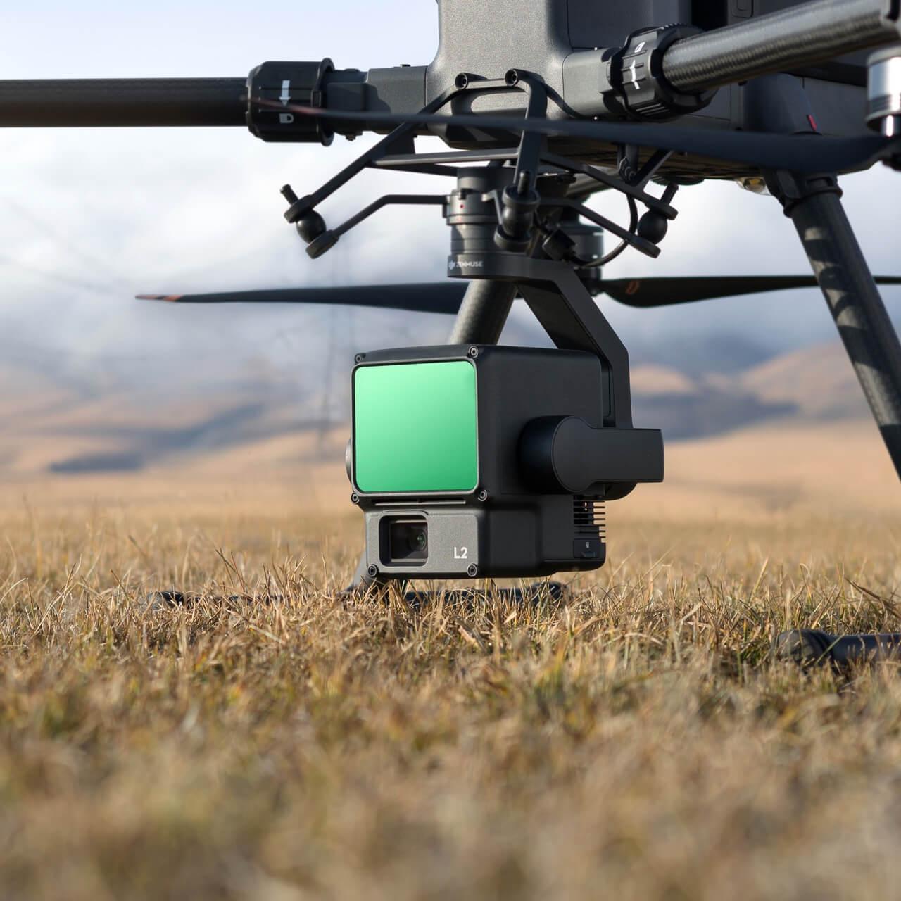
The lidar used above is a Livox AVIA. Which is sort of descent enough, but in terms of accuracy, it falls behind, although it has a really good range, so most people use it for arial drone mapping.
Leica is one very good example which uses multiple cameras (some with very wide fov) and a spinning lidar, and produces some really stunning textured point clouds.
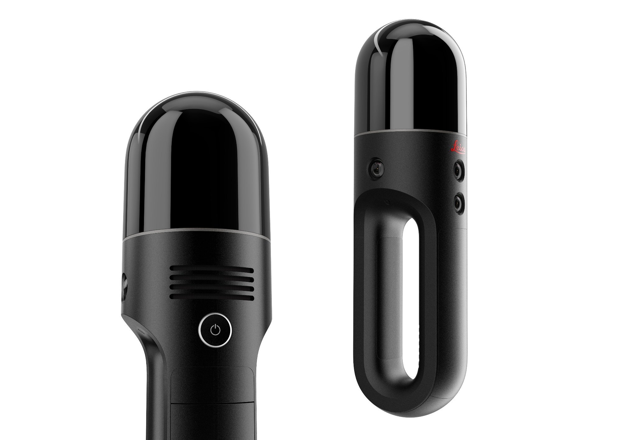
I'll probably cover these readily available lidars like Leica BLK2GO, Faro Orbis, NavVis XGRIDS, FJD and how they work, and what hardware they use.
Now, the challenges here are quite simple, your RGB Camera doesn't give features, the SLAM fails. So environments with extremely low lights, or too much light.
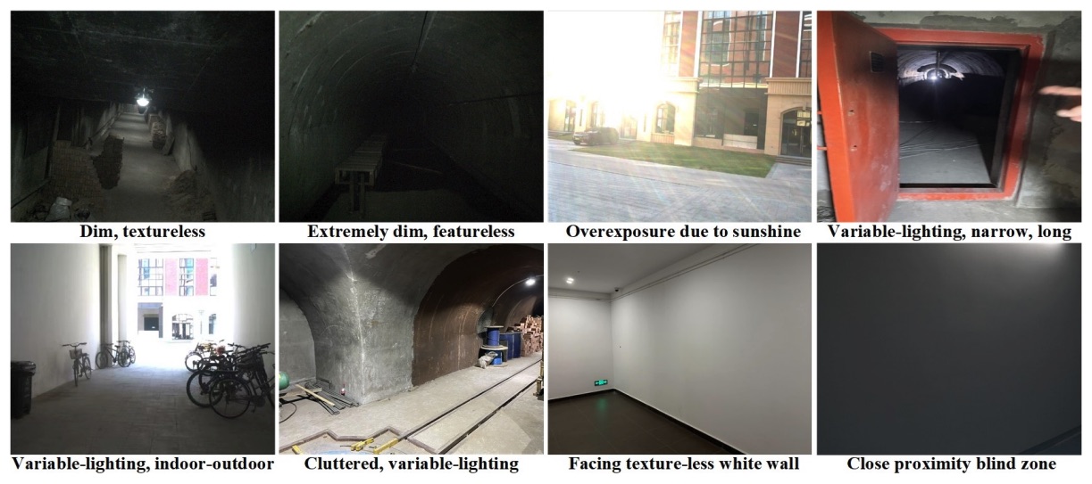
LiDAR
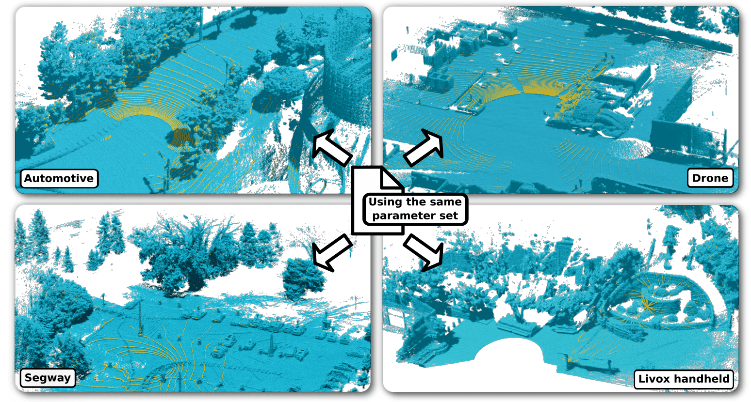
After experimenting with multiple lidar's and performing multiple experiments with scanning patterns, what you need is a 360 deg lidar's with atleast 50-60 deg FOV.
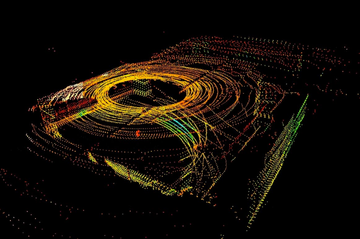
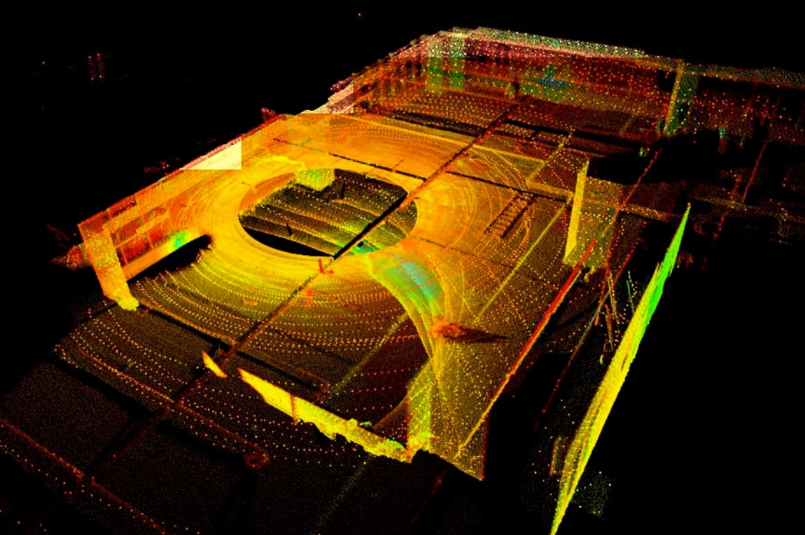
This is the Ouster OS0, the lidar with least noise, and good enough FOV.
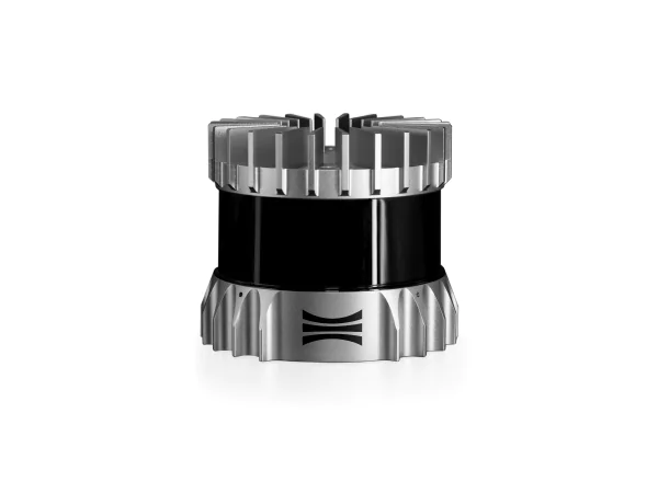
It's sort of a coffee grinder. Brrrrrrr and here's the point Cloud. Note that the device was still.
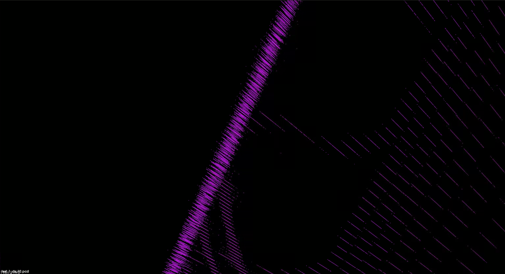
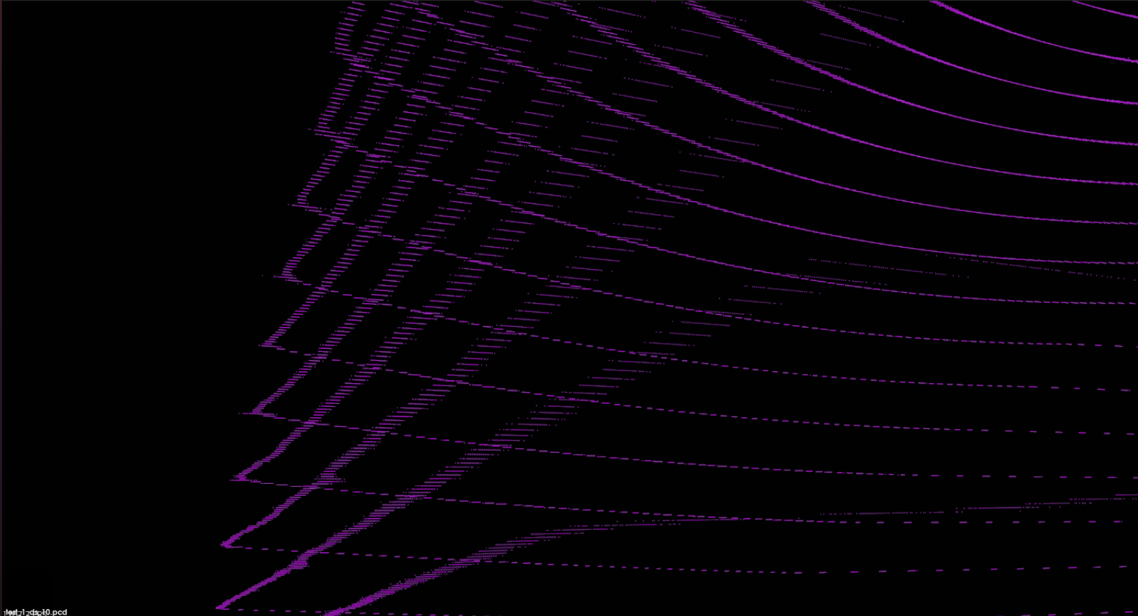
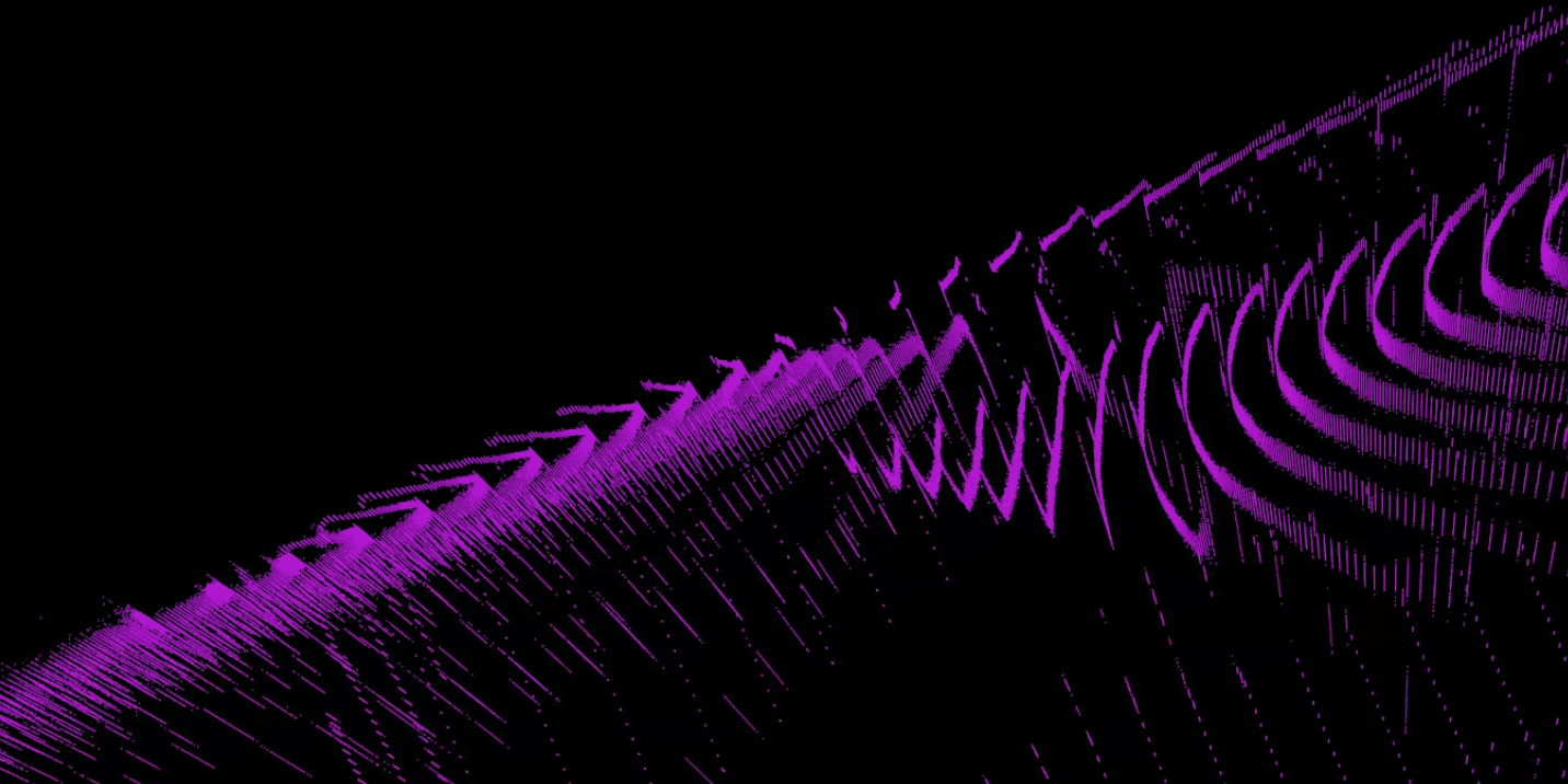
Observe the streaks of points in the scan? That's where the issue lies. It's not solely due to LiDAR accuracy; the vibration of the LiDAR itself also plays a significant role.
It's not unique to Ouster; spinning LiDARs, in general, are prone to vibration.
Ouster is likely an excellent choice for 3D mapping in autonomous driving applications, where accuracy is not a paramount concern. Even if the LiDAR measurement is off by 5cm from the actual value, it's still acceptable.
Even after all these challenges, how is it possible to create 3d maps of entire floors for scan to bim?
Next blog post ;)